

One of the typical projects when we start with Arduino, is to make a traffic light. In this article we are going to give it a twist, we are going to create a smart traffic light. We will simulate that intelligence with two buttons, multiple LEDs and a lot of imagination.
The objective of this tutorial is to show you how to use multiple LEDs with Arduino and also how to integrate it with two buttons. The latter can be replaced by a presence sensor either ultrasound or with infrared.
We are going to simulate a traffic light crossing on a street. Traffic lights are going to have a special feature, they are going to work alone. With the multiple LEDs we will create the lights of the traffic lights. The buttons will simulate presence sensors.
The operation is very simple. When a car comes to a red light, it stops. We will simulate this situation by activating the associated button (as if it were a presence sensor). After waiting time, the other traffic light will turn red and the traffic light where the car is waiting will turn green.
LEDs with Arduino: everything you need to know
The first thing to know before using multiple LEDs is that it is a diode. These types of components are very particular since they only allow electricity to pass in one direction.
But what is that meaning? It is very simple and with practice, you will get used to using them. LEDs have one longer pin than another, that pin is known as the anode (the positive pole). It is where the current has to enter. The smallest pin is known as the cathode (negative pole) and this is where the current of electrons will exit.
LED well connected
With this clear, we can now connect multiple LEDs to our circuit. Now we just need to know what resistance to put. For this we must make use of Ohm’s Law. This Law is the fundamental base on which we must build our circuits.
This Law relates the three basic magnitudes of a voltage, current and resistance circuit. You must know and memorize the formulas that help us calculate one quantity in relation to the others. There is a circle that helps you easily remember this relationship. Covering the magnitude you want to calculate tells you how to do it based on the other two magnitudes.
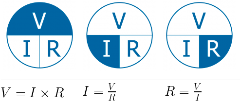
With this formula we can calculate any magnitude. In principle, we need to know two of the magnitudes to calculate the third. In the example of the intelligent traffic light with multiple LEDs and buttons, we will have to calculate it only once. Let’s see how to do it. First, take a look at this circuit:
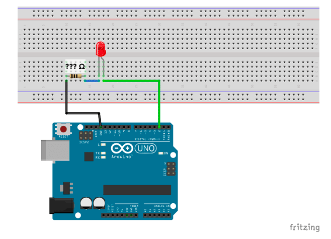
In a series circuit like the one in the example, it does not matter if you put the resistance before or after. Applying Ohm’s Law, you get the same value. At no time does this Law tell us the position of the components. This also applies to multiple LEDs.
It is a very simple circuit, an LED and a parallel resistance. But how do we calculate the value of resistance? We just have to apply Ohm’s Law. We know the voltage, 5 V, is supplied by the digital pins. The intensity can be obtained from the technical characteristics sheet of the Arduino itself as shown below:

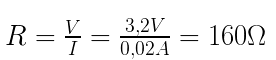
The intensity is 20 mA, which are 0.02 A. The voltage that must fall in the resistance is 5 V less than what the LED consumes, between 1.8 V and 2.2 V. This gives us that the resistance must consume at least 3.2 V.
We already have everything we need to replace the values and calculate the resistance value with the next formula:
Another component that we are going to use and that we must know are the buttons. Thanks to these components we can let the current pass or not. When using a push button with Arduino we have to have certain precautions, especially when we connect the output to a digital pin.
The standard one has four temples. They are connected between them two by two and between them they form the switch. A button is nothing more than a switch that lets the current pass or not.
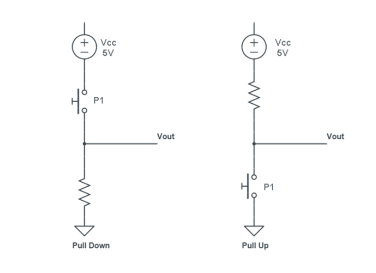
You have probably heard of pull down and pull up resistors. These are two configurations that allow us to have a low state (0 Volts) or a high state (5 Volts) when a cable is outdoors.
This is what happens with the buttons, while we do not press, we have the pin in the air and an indeterminacy occurs. The two possible configurations are as follows.
Smart traffic light circuit with multiple LEDs and buttons
Well, we are already clear about how to use multiple LEDs, buttons and Arduino to create the smart traffic light. Now, I will detail the components that we are going to need:
- Arduino UNO (or equivalent).
- Breadboard, where we connect the components.
- 6 resistors 220 Ω.
- 2 10 kΩ resistors.
- 3 green LEDs.
- 3 yellow LEDs.
- 3 red LEDs.
- 2 push buttons.
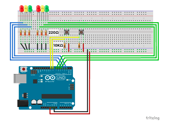
- Multiple LEDs and pushbuttons, mounting the smart traffic light circuit.
In this circuit, when using so many components we have to be very careful with short circuits. This would make the system not behave expected initially. Do it step-by-step and, once connected, test each component to make sure everything works correctly.
The multiple LEDs will form the traffic lights of a junction. The buttons will simulate presence sensors. The circuit would be as follows:
Programming the smart traffic light with multiple LEDs and buttons
The first thing is to understand the problem with extreme clarity in place. We are going to simulate a street crossing with multiple LEDs, which will act as traffic lights, and two push buttons, which will act as presence sensors. The goal is that when a car is placed at a red light, allow it to turn green and close the other light.
To start, we have to start with some initial conditions, which traffic light starts open and which traffic light starts closed? We will start with traffic light 1 open and traffic light 2 closed. To understand us, in the electrical circuit diagram, from left to right will be traffic light 1, traffic light 2, button 1 (simulates the presence of traffic light 1 sensor) and button 2 (simulates the presence of traffic light 2 sensor).
Once a car is stopped at a red light (we simulate pressing its button), it will take a certain time and the sequence will begin to turn off the other light and open yours. Simple, right? Let’s set the initial algorithmic conditions:
A. Standard Conditions:
1.Green LED traffic light 1 on
2.Red LED traffic light 2 on
3.Traffic light 1 active
B. Check that traffic light is active
1.Traffic light 1 active
1.1.Check push pin 2
1.1.1. If pressed
1.1.1.1. Change traffic light 1 to red
1.1.1.2. Change traffic light 2 to green
C. Traffic light 2 active
1. Check push pin 1
1.1.If pressed
1.1.1.Change traffic light 2 to red
1.1.2.Change traffic light 1 to Green
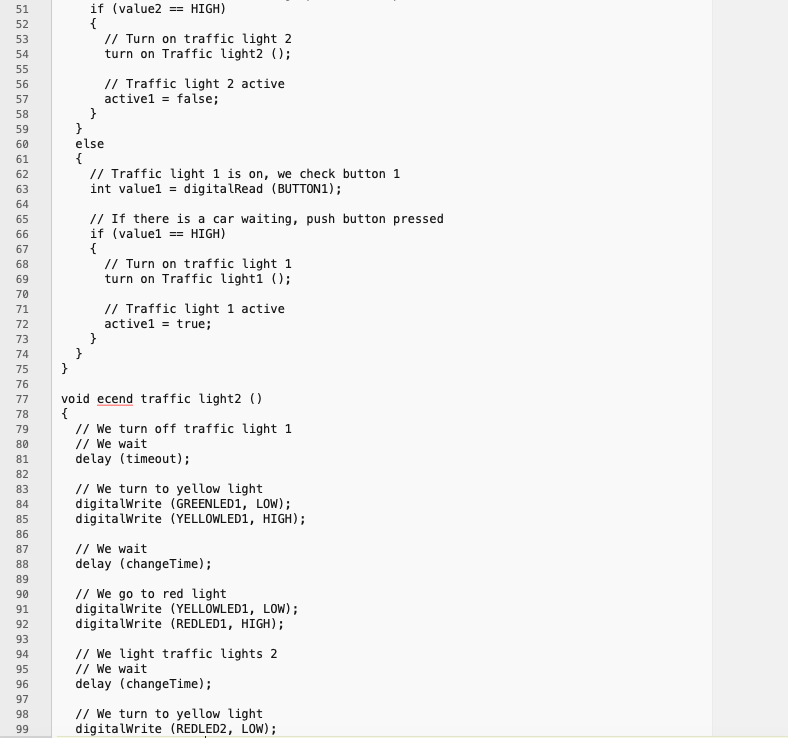
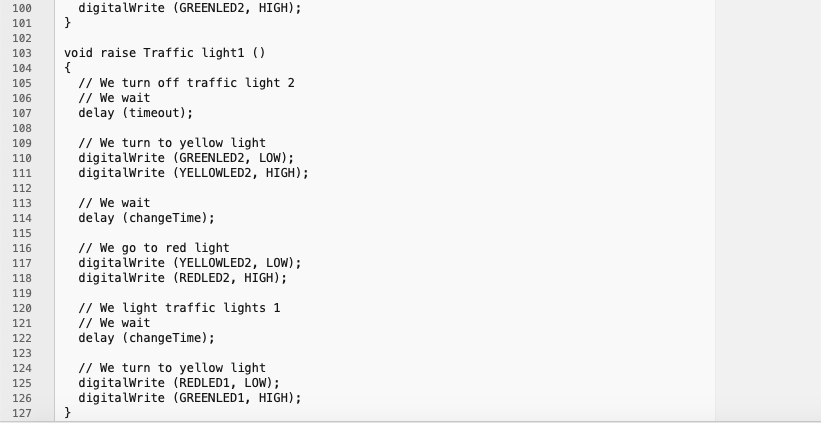
Final Code