In this article, I am going to explain how we can design and assemble a battery charge meter through the assembly of a circuit with Arduino.
It is very common to have various electrical devices around the house that use batteries. Sometimes, we might doubt if the device is broken or the batteries are exhausted.
Battery Charge Meter with an Arduino Board
We will use Arduino to read the voltage supplied by a battery through an analog input. Depending on this voltage, we will light a LED of one color. If the battery is new, a green LED will light up. If the battery is not new and part of its energy has been consumed, we will light a yellow LED. Finally, if the battery is dead or does not supply enough voltage, we will light a red LED.
We must be very careful with the type of battery that we are going to measure. It is very dangerous to supply more than 5V to the Arduino analog pins. If what we want is to measure batteries, we can only do it with AA, AAA, C, and D batteries. They are those used in television controls, toys, and even to power Arduino.
Be careful with a 9V battery, the square ones. As I have said before, these batteries far exceed the 5V limit. We must also be careful with the batteries since it will depend on the voltage they supply. Check it out before connecting anything that it really is less than or equal to 5V.
Arduino components that we are going to use
Let’s see what kind of components we need for this circuit.
1. Arduino UNO or any Arduino board
2. Breadboard where we will connect the components
3. Cables for the connection between the components and the board
4. 3 220 Ω resistors
5. 1 10 kΩ resistor
6. 1 5mm red LED
7. 1 yellow 5mm LED
8. 1 green 5mm LED
As you can see it is a very simple circuit. With 3 LEDs and 4 resistors, it is enough to build a battery charge meter with Arduino.
Building the circuit with Arduino
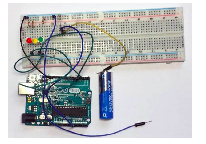
Once all the information has been collected, we proceed to the assembly. In the following image, you will be able to observe how you should connect the different components. Pay special attention to the resistors.
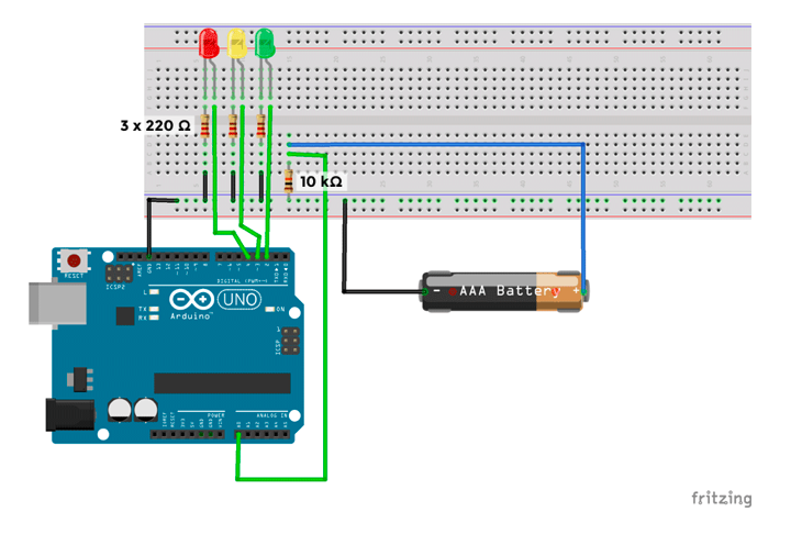
Let’s see how the components have been connected:
The first items to focus on are the LEDs. Each one is connected in series with a 220 Ω resistor to extend their useful life. The green LED is connected to pin 2, the yellow LED is connected to pin 3 and the red LED is connected to pin 4. This is important to remember for the programming part.
To measure the battery I have placed a pull-down resistance. What this type of resistance does is maintaining a low logical state, that is, at 0V. It is important to use this type of resistor since, when we do not have the battery connected to be measured, we have an indeterminate state at the input of the analog pin, which causes it to oscillate and maybe until some LEDs light up. You can try removing this resistance and you will see the result.
The positive pole of the battery is connected to the pull-down resistance and to the analog input A0. The other end of the resistance. Finally, the negative pole of the battery must be connected to the Arduino ground.
Programming the battery charge meter with Arduino
Now it’s time for the programming part. The first thing we must do is raise the problem or the algorithm that we want to achieve. Once we have it clear we can start programming. Remember that an algorithm is a sequence of ordered steps that we must follow to achieve a goal. In this case, our goal is to measure the charge of a battery with Arduino.
Algorithm
In this section I will detail the steps that we must follow without writing a single line of code, we will do that later when we are clear about what we have to do.
1. Read the analog pin where we have connected the battery
2. Calculate the voltage for the value it has given us
3.Evaluate the voltage
3.1 If it is greater than or equal to the maximum threshold
3.1.1We turn on green LED
3.2 If it is less than the maximum threshold and greater than the average threshold
3.2.1We turn on the yellow LED
3.3 If it is less than the average threshold and greater than the minimum threshold
3.3.1We turn on the red LED
3.4 In any other case scenario
3.4.1 We do not light any LEDs
4. We turn off all LEDs
Now we will analyze the algorithm that we are going to implement in order to conclude that the use of 3 thresholds:
• Maximum threshold: It will indicate that the battery is fully charged.
• Medium Threshold: From this threshold to the maximum threshold the battery has been used but still has power.
• Minimum threshold: From this threshold to the average threshold the battery does not supply enough energy. Below this threshold, we interpret that there is no battery connected.
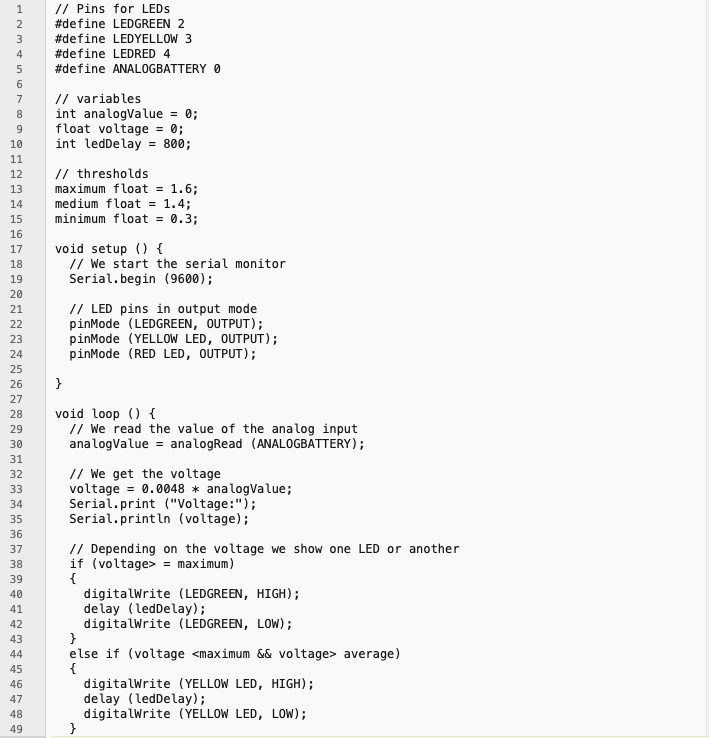
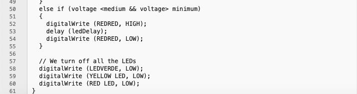
Final Code